Shopping cart


Your cart is empty

$0,00

0

964/993 Rear spoiler mechanism

See our new Electrical test further down on the page

Worm gear Bearing failure

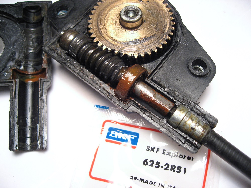
The Porsche 964/993 back spoiler mechanism is equipped with a ball bearing that will fail over time due to moisture and corrosion. A damaged bearing will be heard as a grinding noise or rattle when the spoiler move either up or down. A new bearing is very cheap compared to changing the complete gear mechanism.

Easy access
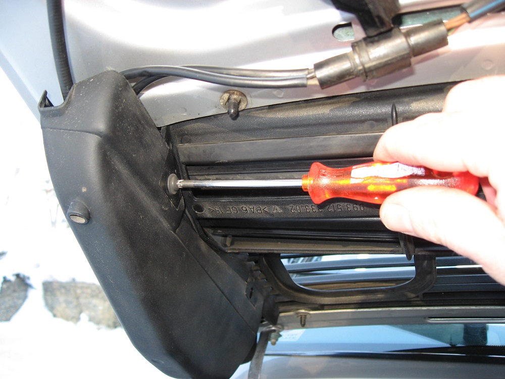
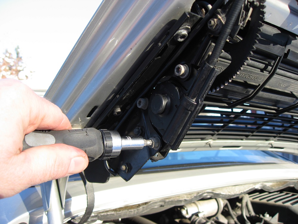
Remove two screws and undo the plastic fasteners on the outside. Remove the three hex screws. Remove the splitted plastic ring. It is easy to get to the different components in the spoiler mechanism, all of them are mounted under a plastic cover mounted on the engine lid. Two screws and three plastic retainers hold it in place.
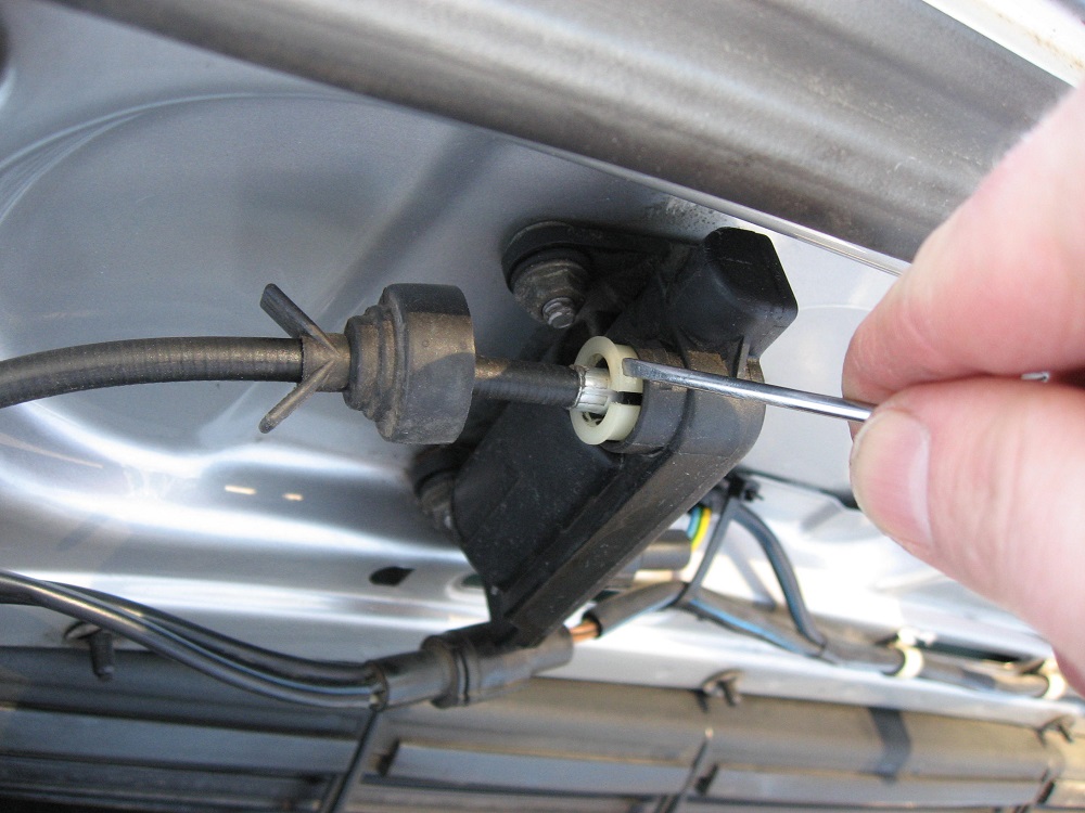
The motor and gear housing are connected with a wire, and this must be removed to be able to detach the gear. Pull off the rubber cap and loosen the white plastic ring with a small screwdriver. This ring is splitted and easy to pull out from the motor housing. Detach the gear housing by removing the three umbraco screws.

Gear housing
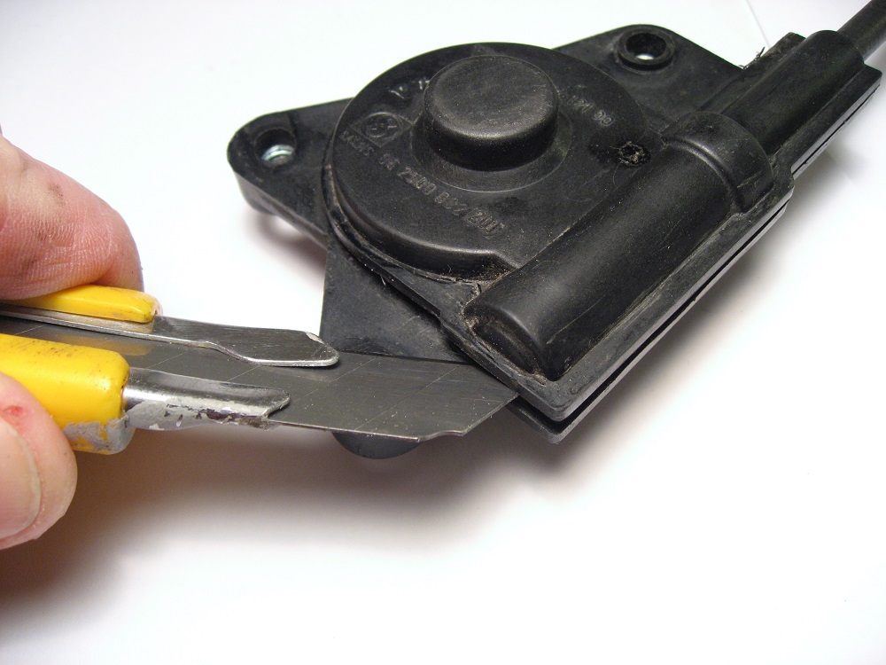
Open the glued gear housing. The plastic cover is made of two pieces and these are glued together. Work around the edge with a spatula or knife until the top half comes off. This may take some force.
Clean the gears with alcohol or similar. Remember to clean the connecting wire to the motor as well.

Worm gear axle disassembly
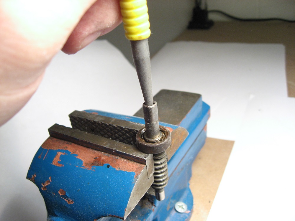
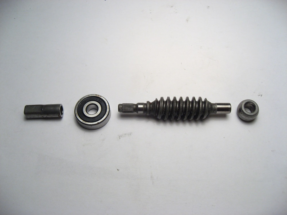
Hang the axle loosely in a vice and punch through the square sleeve.The ball bearing must be pressed off the axle. The easiest way is to hit the axle with a punch or similar while the whole assembly hangs loosely in a vice. Be sure to use a thin and long enough punch so the square metal sleeve is not damaged. You must not hit the metal sleeve, only the axle inside it.

New bearing
The new ball bearing should be of a more sturdy sealed type, and it can be bought on eBay or ball bearing shops. It is a standard 16x5x5mm bearing, often called 625-2RS or 625DD.
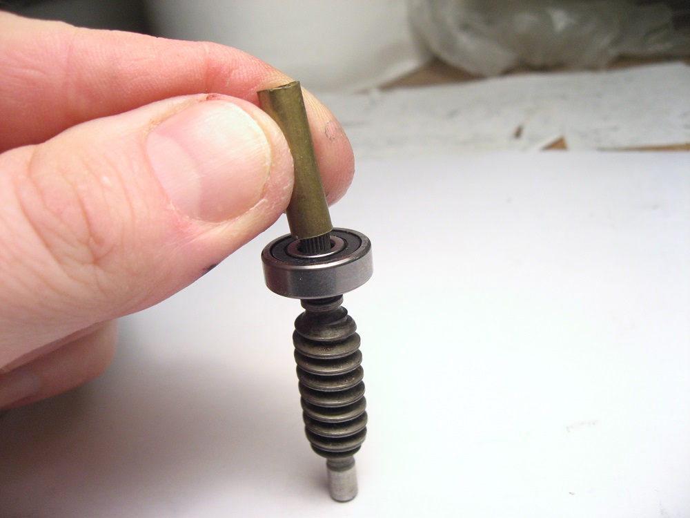
The bearing must be pressed onto the axle until seated against the flange. This can be done by using a brass tube or similar and press it on in a vice. Be sure to press fit the square metal sleeve onto the axle as well.

Grease on all components in the gear as well as the connecting wire and glue the casing halves with Araldite or other slow-curing two-component glue. Please note: Cyancrolate super glue will not stand up to the mechanical stress in the casing.
Voilá, job done in 30 minutes, almost no cash spent! A high-quality sealed 625-2RS ball bearing can be found in our web shop.


Full test of all rear spoiler electric components


Here we describe how to test the rear spoiler power supply, motor and switches. 

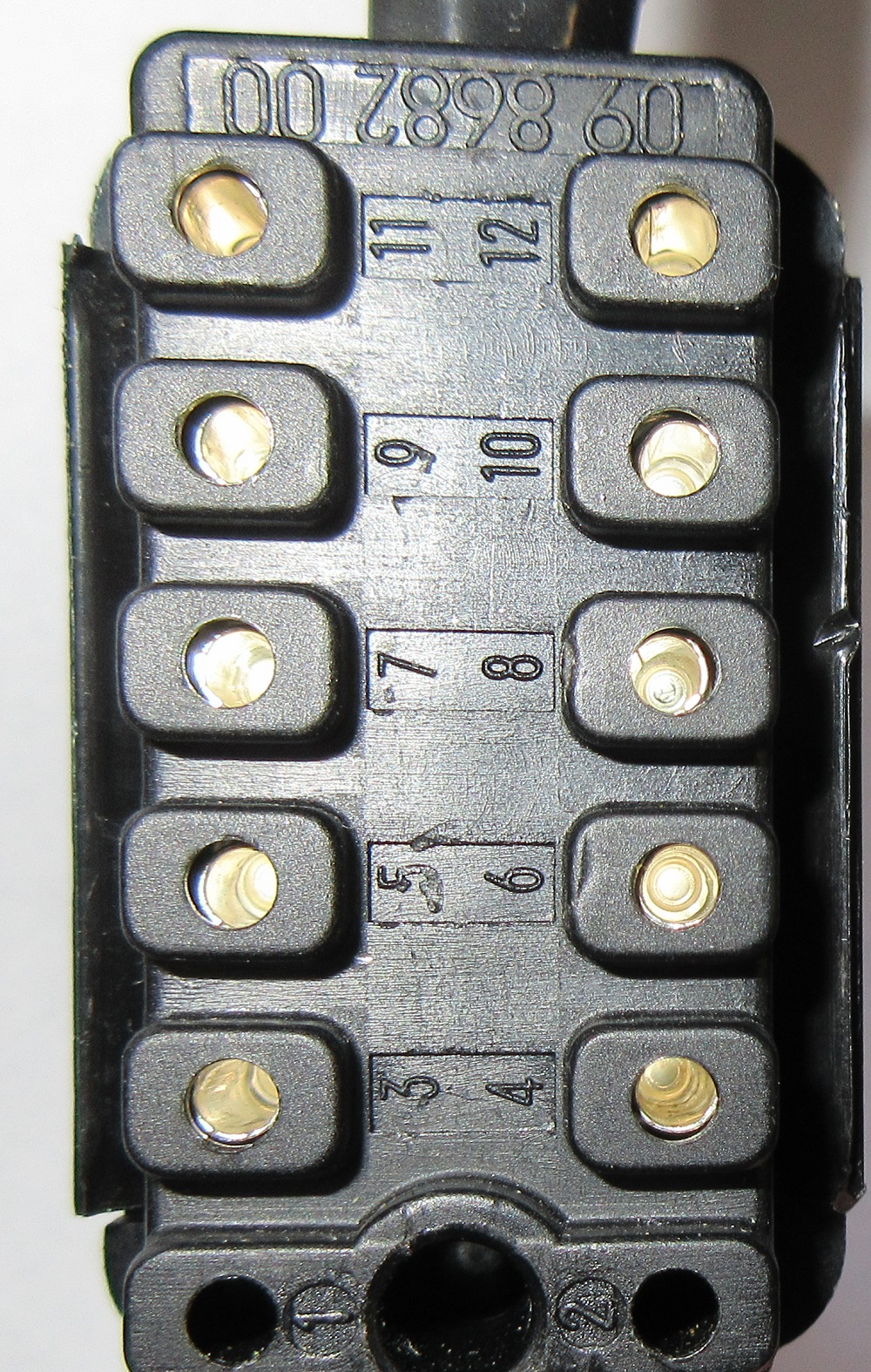
Remove spoiler control unit, measure with voltmeter on harness connector, pin numbers is printed on the harness connector:

  • -GND at pin 5
  • -Check for permanent +12V on pin 6
  • -Check for switched +12V on pin 7 when ignition is on

Centre console manual operation switches

Measure with ohmmeter

  • -Pin 11 and pin 10 shall have continuity when you press/turn Down switch (otherwise no contact)
  • -Pin 11 and pin 9 shall have continuity when you press/turn Up switch (otherwise no contact)

Mechanism end switches

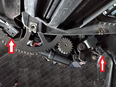
Measure with ohmmeter, see picture for microswitch placement, red arrows

  • -Pin 9 shall be connected to GND if you press the Extended microswitch in the spoiler (otherwise no contact)
  • -Pin 10 shall be connected to GND if you press the Retracted microswitch in the spoiler (otherwise no contact)

Motor output test, voltmeter

Connect the control unit to the harness connector. Remove the harness connector top lid. Be very careful to not pull the wires, the pins can easily be removed from the connector. Having the control unit inserted helps holding the pins in place. Connect the voltmeter to pins 3 and 4 (motor output)

  • -Press/turn Up switch, you should read 12V and motor shall extend the spoiler
  • -Press/turn Down switch, you should read -12V and motor shall retract the spoiler
If the control unit is suspected faulty, an alternative is to connect a wire bridge beween pin 5 (GND) and pin 3. (Motor +) Also, insert a wire bridge from pin 6 (12V) to pin 4. (Motor-)  The spoiler motor shall run in one direction. To test the motor running in the oppsite direction, bridge pins 5-4  and 6-3.  Be very careful doing this, there will be no automatic stop of the motor when the spoiler reaches the end positions, and you risk damaging drive gears or motor. You can disconnect the motor drive cable to avoid this problem.