Shopping cart


Your cart is empty

$0,00

0

964/993 HVAC test procedure

DIY test procedure for most ventilation components in the 964/993

Many Porsche 964 and 993 owners store their cars during winter time, and it might be a good idea to run a full check of all HVAC components before taking out the car for a new driving season.
We get lots of questions on how to run a full check of all HVAC components, and have made this DIY guide to take you through the process. This system check is done in 15-30 minutes and does not require any special skills or tools. Almost all tests can be done by observation and by maneuvering the Climate Control Unit (CCU) controls.

Do these tests with ignition on, and cold engine. We advise to not start the engine, it is easier to hear fans and servo motors without the engine running. Testing the A/C compressor clutch needs the engine running.

Electric fans


Rear (AUX) fan in engine compartment

The rear fan is placed on the left side of the engine compartment, and has two purposes: Blowing heated air to the cabin and cooling the engine when needed. Do this test with a cold engine to avoid the automatic cooling function. Ignition ON.rear_fan

Set CCU fan speed knob to 1 and temperature control to maximum. The rear fan shall start and run in low speed
Set CCU fan speed knob to 2 or above. The rear fan shall switch to high speed
If the rear fan does not work, check fan motor and fuse. The fan motor bearings wear out and seize, causing excessive current and the fuse to blow. The fan relay also wears due to the high motor current. If the fan does not run in low speed, or oscillates on high speed, you have a problem with the rear fan low speed resistor. See here for details, chapter: Rear (AUX) fan.

Main cabin blower fans


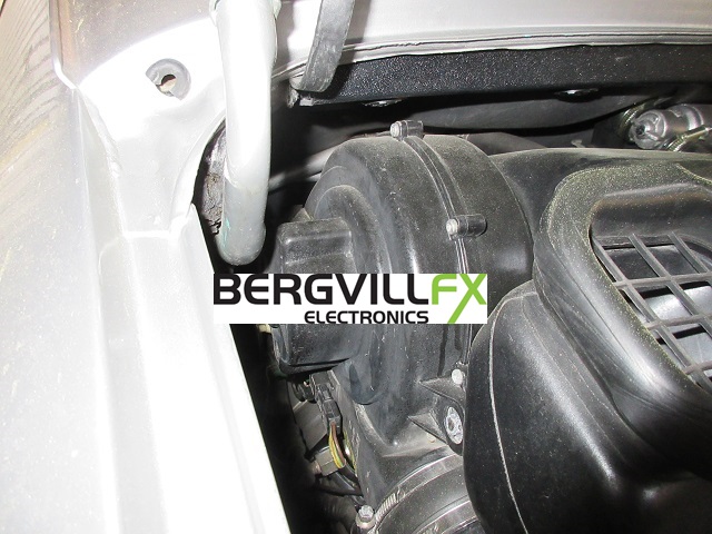
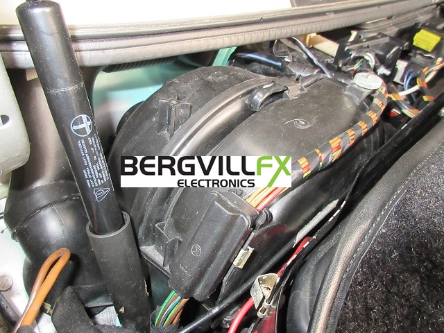
The two main blowers are placed on each side of the air box in the luggage compartment, just below the windscreen. Remove the black plastic cover to reveal the rounded fan housings.
Set CCU temperature control to minimum, adjust fan speed knob
The two main blowers shall change speed according to the fan speed setting. In early 964 vehicles the fan never stops completely. (same speed on 0 and 1) On later 964 (and all 993) models, it is possible to stop the fans on fan speed 0. Read about common faults here, and details on the fans here, chapter: Front interior fans.

Set CCU temperature control to maximum, adjust fan speed knob
If the main blowers now does not run on full speed, or periodically are shut down, you most probably have a problem with the rear fan. The rear fan is supervised by the CCU, and if it does not work on both speeds, the CCU will shut down the main blowers to indicate this. See above and here for details, chapter: Rear (AUX) fan.

Oil cooler and A/C condenser fans

The oil cooler radiator fan is placed in the right front fender, and shall run in two speeds depending on the cooling needs. Relay R04 contains two relays for low and high speed. You can use the relay or a wire jumper to test the fan circuit. Pop off the relay plastic cover, and depress the two relays with your finger while it is installed in its fuse box position. You can also remove the relay and use a wire jumper to jump 30 and 87 to run the fan at high speed, or terminal 30C and 87C for low speed. Terminal numbers are printed on the relay bottom. If the fan does not run on low speed, check the low speed resistor. See this web page for details.

Do the same test for the A/C condenser fan, placed in the left front fender. This is relay R14, next to R04.

Climate Control Unit fan


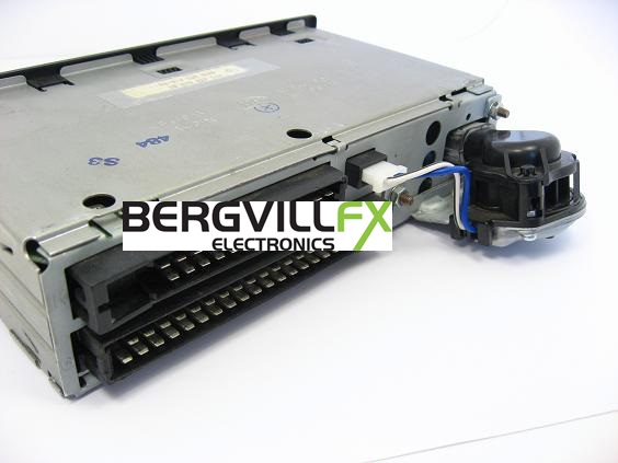
The CCU fan is mounted at the back of the CCU. It shall start at ignition on, and run for up to 20 minutes after ignition off. You can reach it from under the dashboard to feel it running, or just listen for the humming at the back of the CCU. This fan is known to wear out and make rattling noises, and the magnets weaken so it will not start. See here for details on what happens when it fails. We sell a replacement fan here.

Ventilation flap servo motors


The five HVAC servo motors control the air flow in the dashboard. Three of them move all the time to maintain the desired cabin temperature: The fresh air and the two mixer servos. These are the ones that is most likely to fail first. The internal motor wears out and short circuits, creating internal overcurrent damage. The CCU stops any motion in a servo if it detects a failure. See here for common problems, and here for details on the servo internals, chapter: Electric flap servos.

Fresh air servo


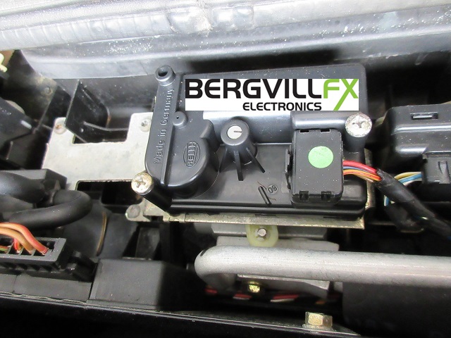
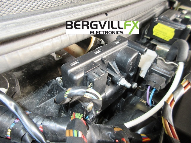
The fresh air servo is placed at the middle of the air box in the luggage compartment. Remove the black plastic cover to see the servos.

Turn temperature knob to min and max, the fresh air intake servo should open and close.
The servo shall close at ignition off, the white plastic arm is then visible and shall point in car forward direction.


Mixer servos


The 964 mixer servos are placed on the left and right side of the fresh air servo. They have arms with ball links, and shall move simultaneously.

Turn temperature knob to max and min, the mixer servos shall open and close by rotating the output arms.


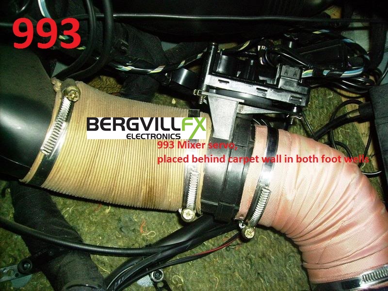
The 993 mixer servos are placed on the sides of both foot wells in the cabin, mounted where the hot air hoses come up from the door sills. It is a bit difficult to spot any motion of the flap inside the flap assembly without removing it from the hose. You can also just listen for the servo motor whirring when operating, even with the carpet wall in place.

Turn temperature knob to max and min, the mixer servos shall open and close by rotating the flap inside the housing.


Foot well servo


The foot well servo is placed on the left side of the air box. (seen from the car seats) Its output arm is barely visible, but you can see the metal rod connection to the flap inside the air box.

Move lower slide knob to the right and left, the footwell servo should open and close.


Defrost servo
The defrost servo is placed on the right side of the air box, with a white plastic rotating output arm.

Move upper slide knob to the right and left, the defrost servo should change air flow between middle air nozzles and windscreen.

Resirculation flap

Porsche 964
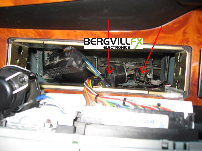
The resirculation flap is placed under the dashboard and can be seen from the foot well, but also through the CCU opening. The 964 and 993 MY 1994 and MY 1995/1 models have a spring loaded resirc flap. It will open due to the slight vacuum caused by the two main blowers when all other air supply flaps are closed. Ensure that the flaps are not just hanging loose, but have a light spring load to close them.

Set CCU fan speed knob to 2 and temperature control to minimum. A/C OFF
Press Resirc button on CCU, the fresh air flap shall close to stop the air flow of outside air, and the resirc flap shall open to draw air from the cabin.


Porsche 993 resirc flap


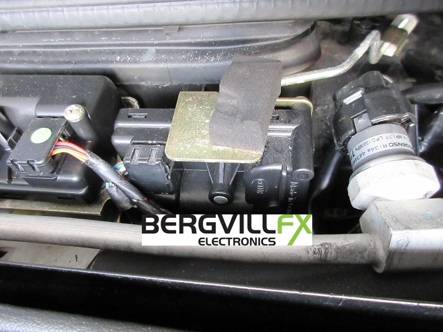
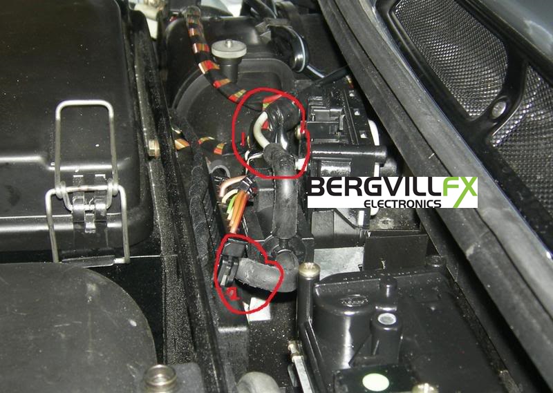
The 1995/2 and later 993 models have a resirculation flap that is operated by a vacuum actuator. The actuator is controlled by a electric solenoid valve, placed between the Fresh air and Defrost servos on the air box.


993 resirculation flap solenoid valve

Start the engine to build up vacuum. Set CCU fan speed knob to 2 and temperature control to minimum. A/C OFF
Press Resirc button on CCU, the actuator shall immediately pull the resirc flap open. You should also hear the solenoid valve clicking.
Press the accelerator, the vacuum then weakens, but the resirc flap shall not move. If it does, look for a leak.
If there is no actuator movement, you most probably have a vacuum leak somewhere. Check that the vacuum hose is connected to the actuator with the rubber bend, and that both hoses are connected properly to the valve. If OK, you have to look for the leak in the engine bay. See here for details, chapter: Vacuum operated resirculation flap

A/C compressor


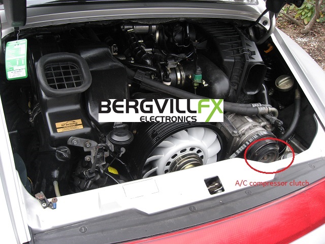
The A/C compressor starts when the inbuilt electric clutch engages. In normal operation the clutch will activate in intervals of 10-30 seconds, depending on the ambient temperature. The 993 CCU models have two A/C buttons, use the small snowflake button for this test. Do this test in an environment with about 20 degrees C ambient temperature. If ambient temp is below 10 deg C, the evaporator sensor can disable the A/C clutch as it normally does in intervals when in normal A/C operation.

The CCU will activate the A/C compressor engage output if the following conditions are met:
-One or both A/C switches ON
-Fan speed setting above 0
-Evaporator sensor reading above 4°C
-Outside temp sensor reading above 4°C (993 only)
-Engine running
-Terminal X power feed OK (Term X must also been off during cranking)

Start the engine, set CCU fan speed knob to 2 and temperature control to minimum.
Press the A/C button, the compressor clutch shall engage within a few seconds. Also check that the Condenser fan start on low speed immediately when the A/C button is pressed.
The complete compressor inner hub can be seen spinning when the clutch is engaged, and the hub is inert when the clutch is not active. If the clutch does not engage, you most probably have a leak in the A/C system soemwhere, and the pressure switch has disabled the clutch. See here for details, chapter: A/C compressor operation